Week 1 Physical Computing Lab
Conducted Week 1 Labs with Junoh Yu and Sumi Lee
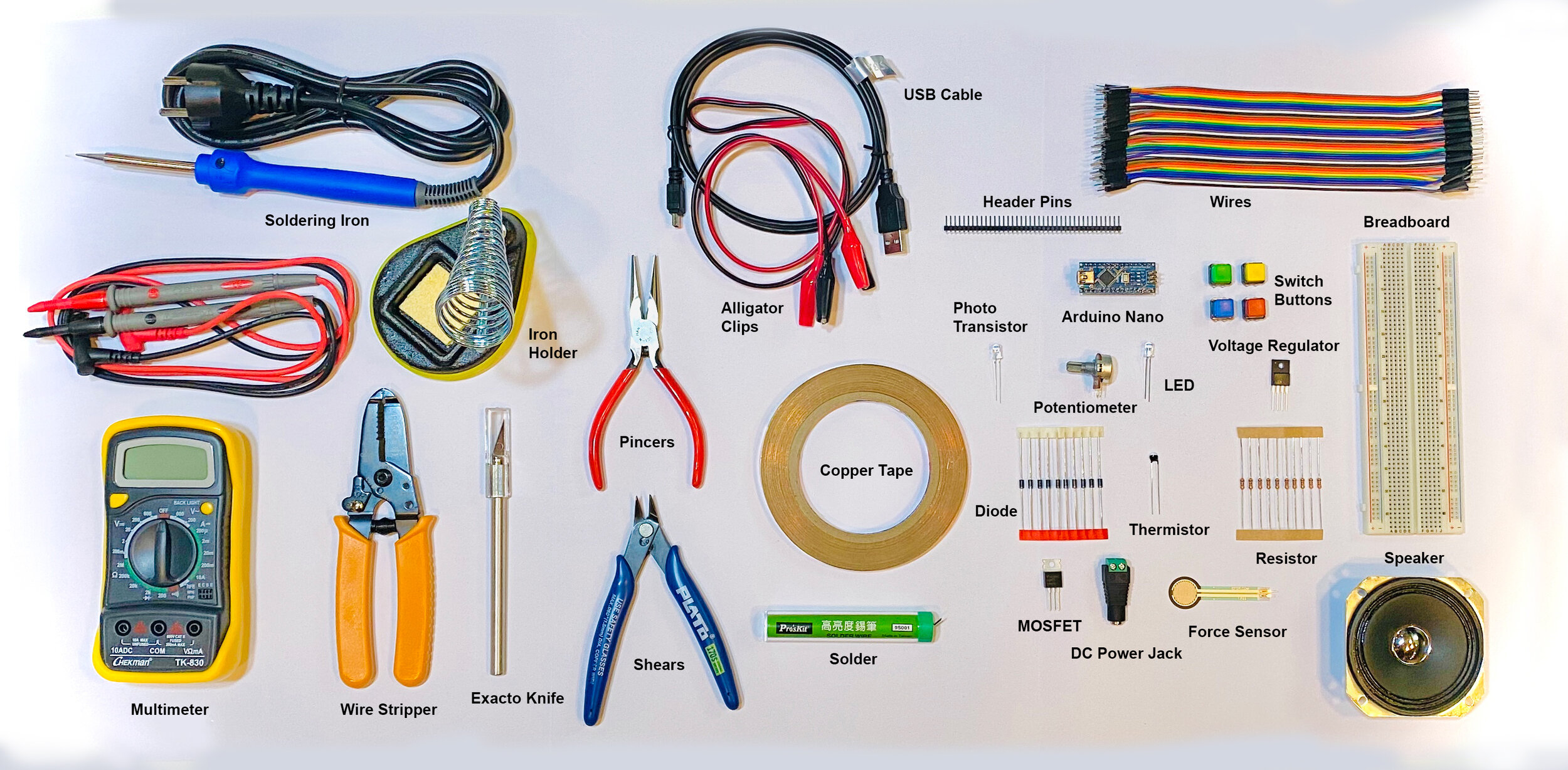
Components Setting up a Breadboard Electronics and Using a Multimeter Switches and Pushbuttons
Lab: Components
Lab: Setting Up a Breadboard
Setting up and Powering the Breadboard


We did not have the 7805 5-Volt voltage regulator and instead used the KIA78R33PI 3.3-Volt voltage regulator
After studying all documents and videos, we set out to build our breadboard.
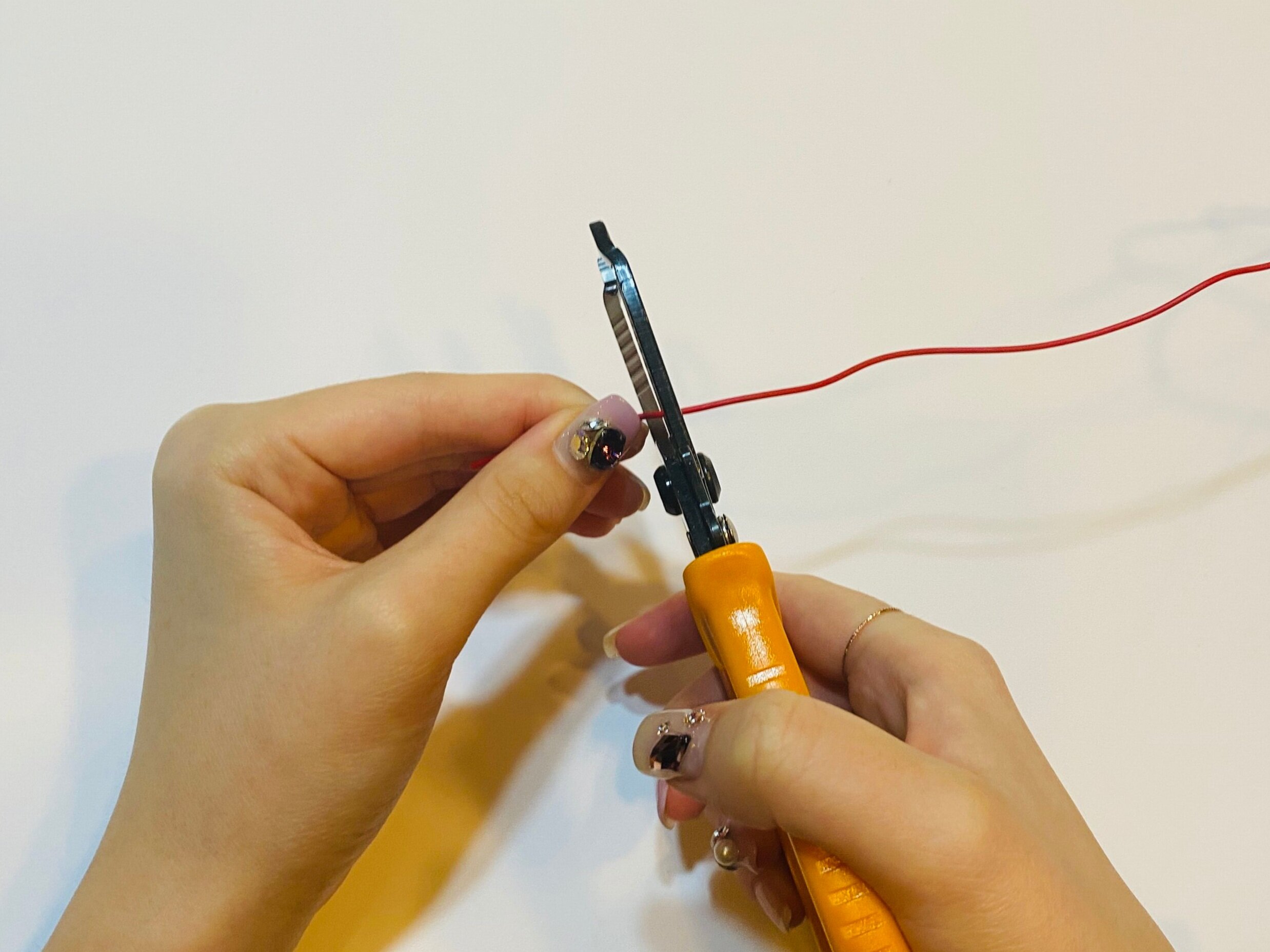
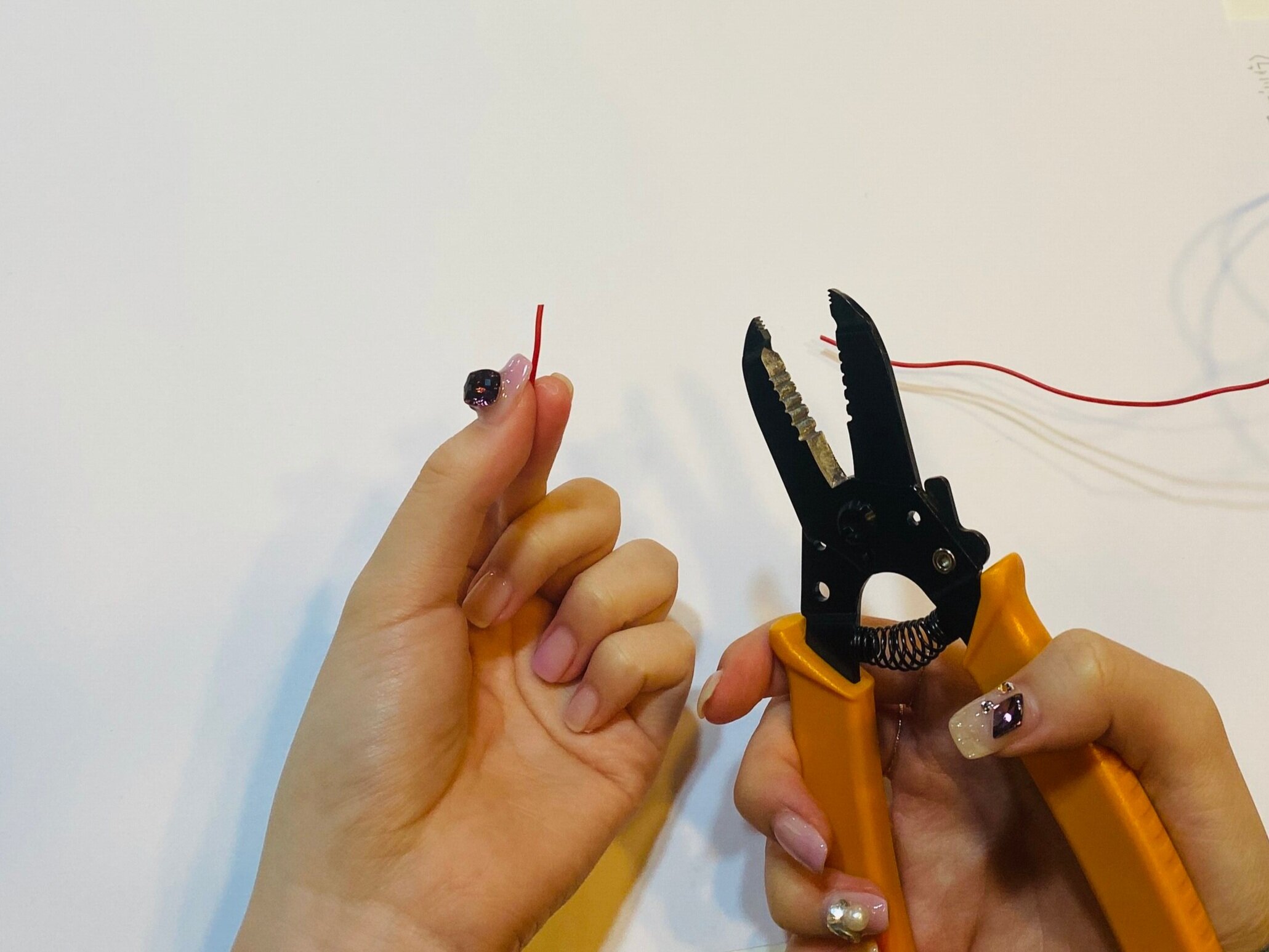
We realized early on that the wires we originally prepared were too long and becoming very messy. Therefore, we purchased spools of wire to cut and strip them ourselves.
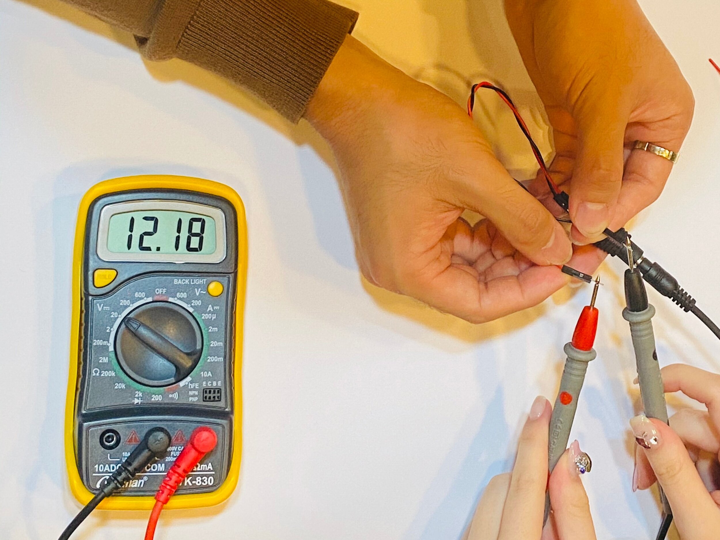
We then tested the power to make sure we were getting around 12 volts.
Will it Light?
Model 1
Yes, it will light because it is wired correctly as a closed circuit in series.
Model 2
No, it will not light because the circuit is not closed. According to the anatomy of a bread board, there is a break in the center of the board. Therefore, the metal strip connected to the resistor is not connected to the metal strip connected to the light.


Model 3
Yes, it will light because it is wired correctly as a closed circuit in series. This model is the same as model 2 with an addition of a wire. This wire connects the left strip, connected to the resistor, to the right strip, connected to the light, effectively closing the circuit.
Model 4
No, it will not light. The light is placed in a parallel circuit. Since current follows the path of least resistance, the current will bypass the light and go straight to ground.


Model 5
Yes, it will light because it is wired correctly as a closed circuit in series. Past circuits required the current to go around the breadboard. This circuit allows the current to go through the light bulb first and then around the breadboard to get to ground. This circuit also utilizes the light bulb to act as a wire connecting the metal strips across the break in the center.


Lab: Electronics and Using a Multimeter
Testing the Meter


Measuring Continuity (beeeep)
Measuring Continuity Across your Hand
Touching Two Ends of a Wire
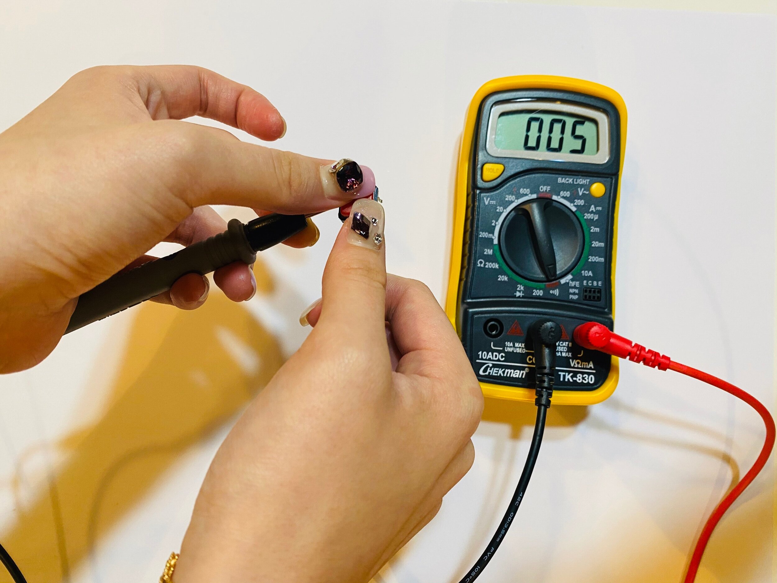
We tested the continuity of a finger. As there is no continuity in a finger, the multimeter calculated 1 and did not beep.
We tested the continuity of a wire. The multimeter beeped and calculated a number close to 0, proving continuity.


Touching Two Points on a Switch
We tested the continuity of a switch. There is no continuity, as shown by the 1 on the multimeter, when the switch is not pressed. However, when the switch is pressed, there is a beep as well as a number close to 0 on the multimeter.
Probing Points on a Breadboard
We tested the continuity of different points on the breadboard. When we tested two points on the same metal strip, there is 0 on the multimeter showing continuity. However, when we tested two points on different strips, the multimeter shows a 1 proving there is no continuity.


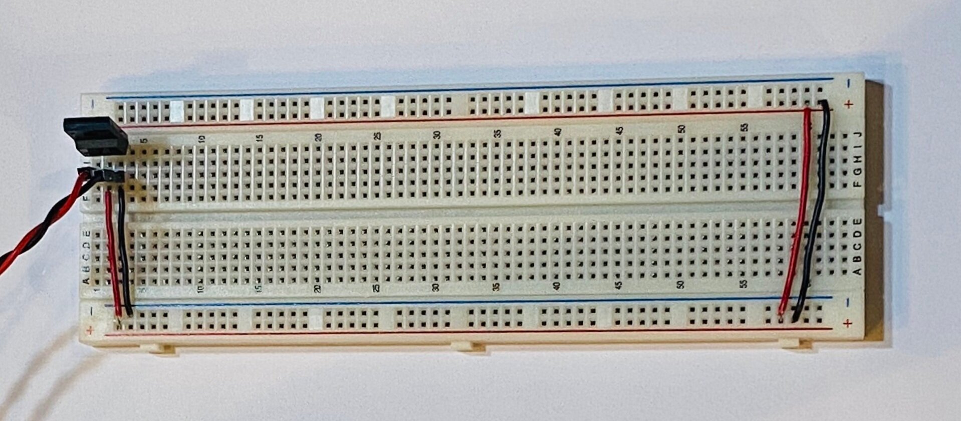
Setup the Breadboard
We tried out two setups for our breadboard. As seen in image 1, we mounted the Arduino nano as our power source. In image 2, we used the DC power jack and a voltage regulator as our power source. We went with the DC power jack and voltage for our subsequent activities.

Measuring Resistance of a Component
Resistance Across your Hand
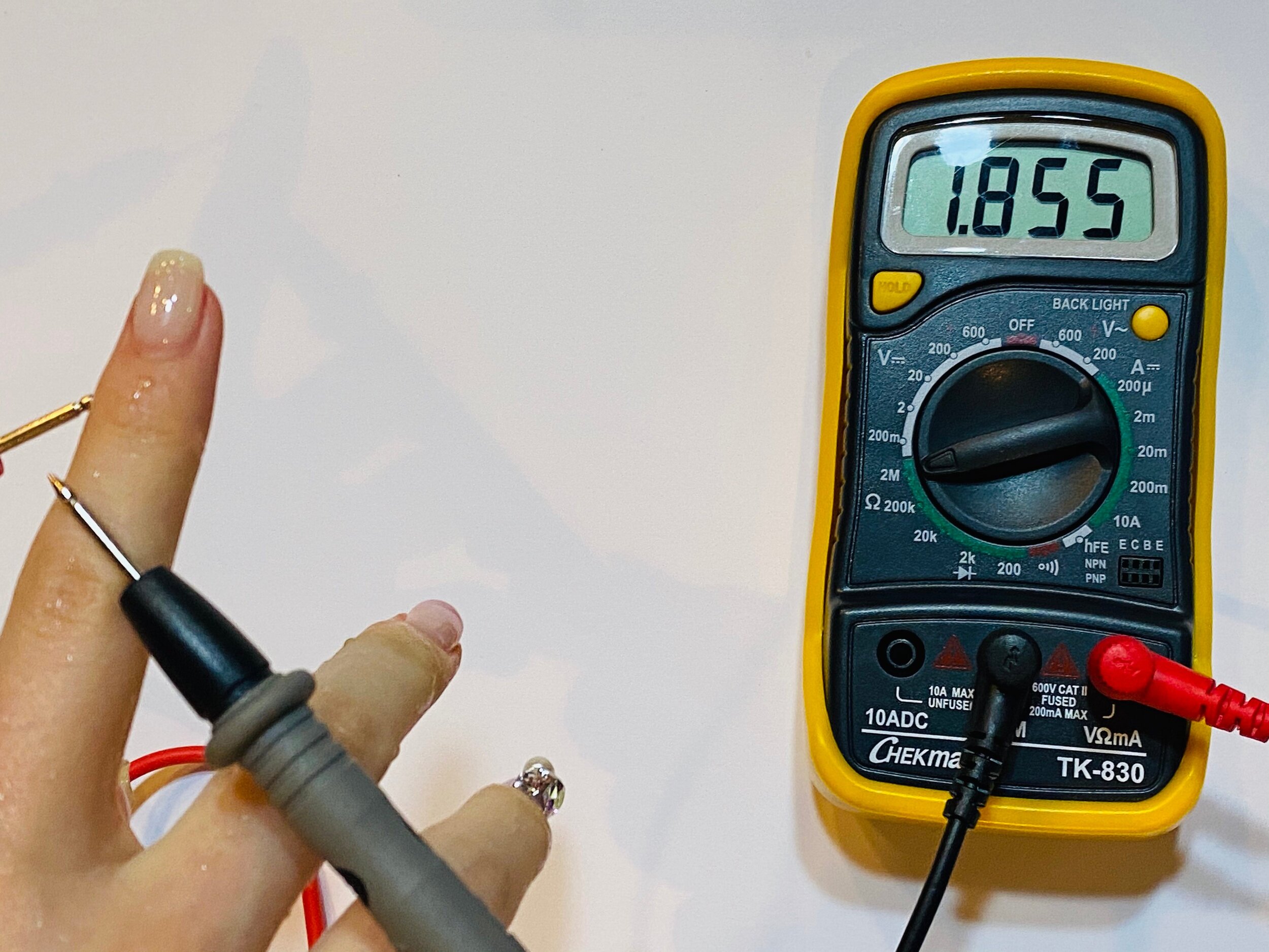
We measured the resistance of a dry finger. The multimeter calculated 1 to show that the resistance is close to infinite. When we measured the resistance of a wet finger, the multimeter calculated a number close to 20 ohms. This is because the water creates a large surface area of contact and creates a connection with the finger to allow electricity to flow.
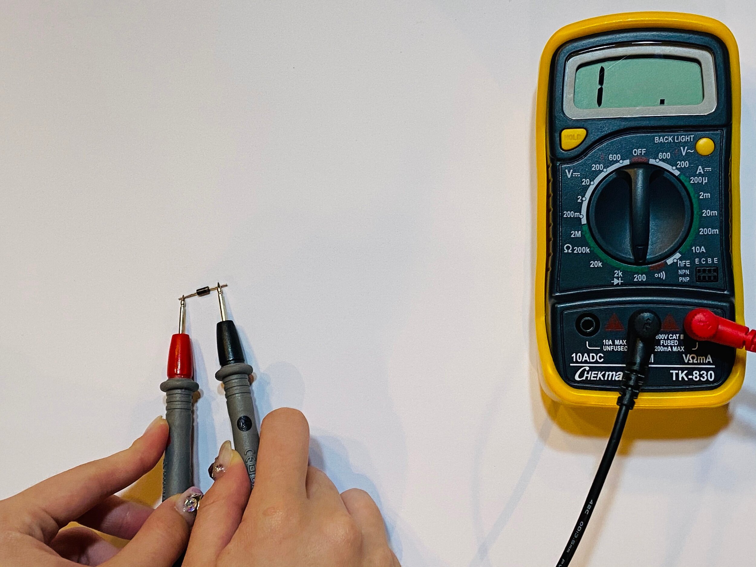
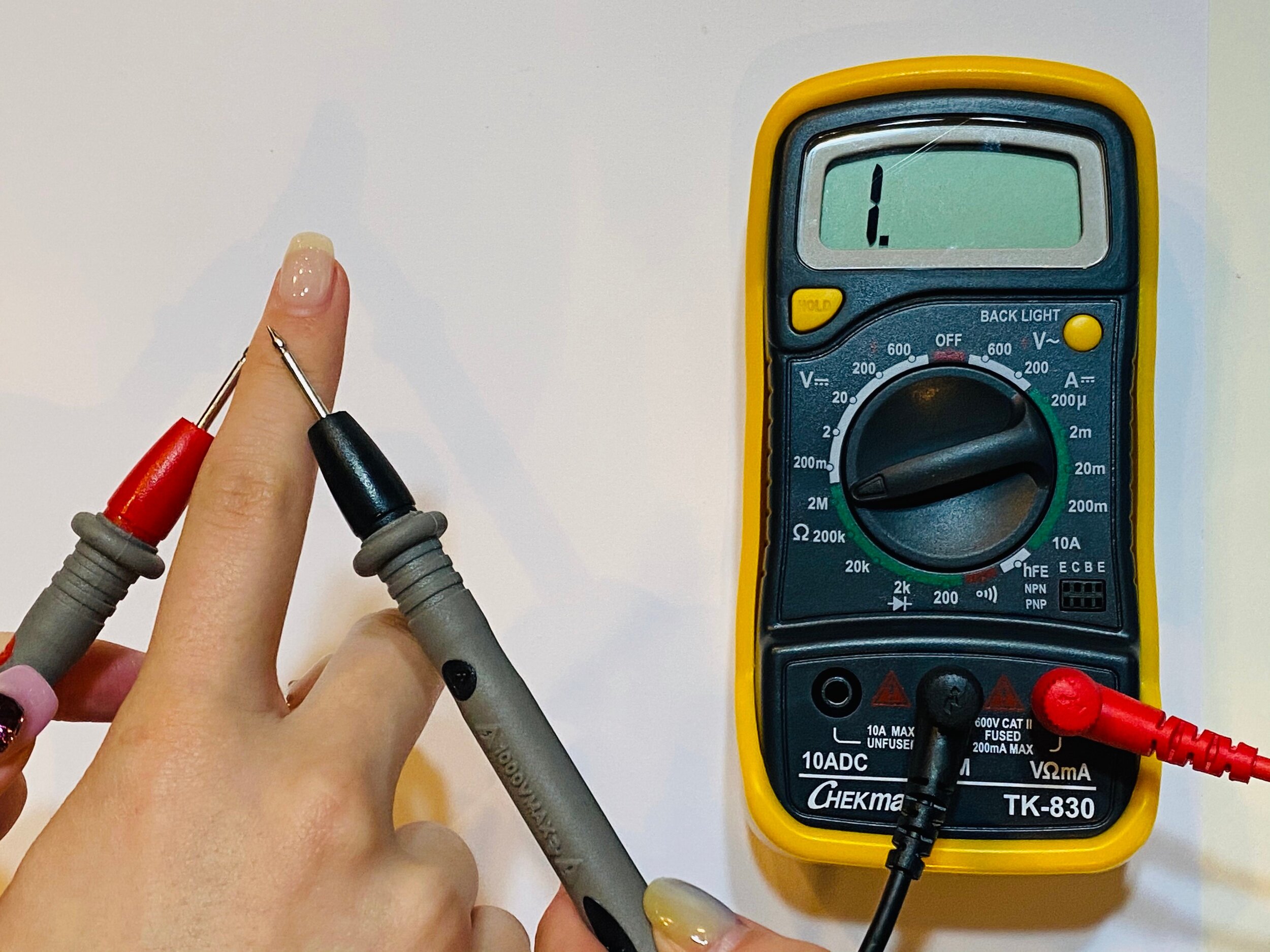
Resistance and Diodes
We measured the resistance of a diode. The two pictures show the forward bias in action. The diode’s resistance is ideally infinite, represented by the 1 on the multimeter. However, when there is a minimum voltage flowing through, the diodes have little to no resistance shown by the low number on the multimeter.


Measuring Voltage
A Switched LED Circuit
Measuring switch


Measuring LED

Measuring Resistor


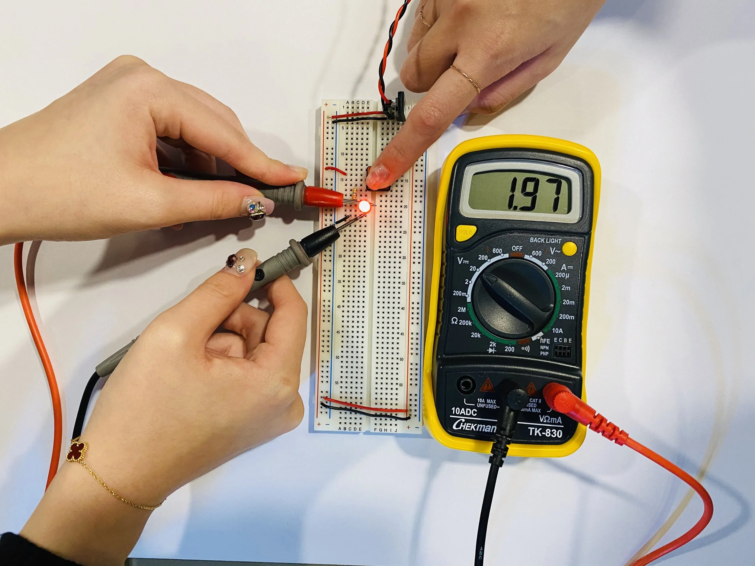
We measured the voltage of components in a switched circuit. When the switch is not pressed, we can measure around 3.02V. When it is pressed, there is no voltage on the switch while the LED has around 1.97V and the resistor has around 1.25V. The switch’s original voltage roughly adds up to the voltage of the LED and resistor when it is pressed. This is because in any given circuit, the total voltage around the path of the circuit is zero since all voltage is used up in the circuit.
3.02V = 1.97V + 1.25VComponents in Series

We added another LED to create a more complex series circuit. The total voltage from power to ground measures to around 3.81V. When the switch is pressed, the resistor measures to around 0.06V, the Red LED measures to around 1.25V, and the Blue LED measures to around 2.39V.
3.81V = 0.06V + 1.25V + 2.39VMeasuring Resistor


Measuring Red LED


Measuring Blue LED


Adding a Third LED in Series

We attempted to create a circuit with three LEDs. However, it does not light up due to not having enough voltage for each LED. Each LED needs about 2V to turn on and in our current setup, each is getting less than 2V.
Components in Parallel/Measuring Amperage


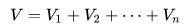
We set up a parallel circuit and measured the voltage across each LED. The voltage were the same across each one. This phenomenon can be explained with the equation:

We then checked the amperage of our circuit by disconnecting one of the LED’s ends and placing the meter in series with the component.


Generating a Variable Voltage with a Potentiometer
We set up a potentiometer to work with an LED and then measured the variable voltage with the multimeter.
Lab: Switches and Pushbuttons
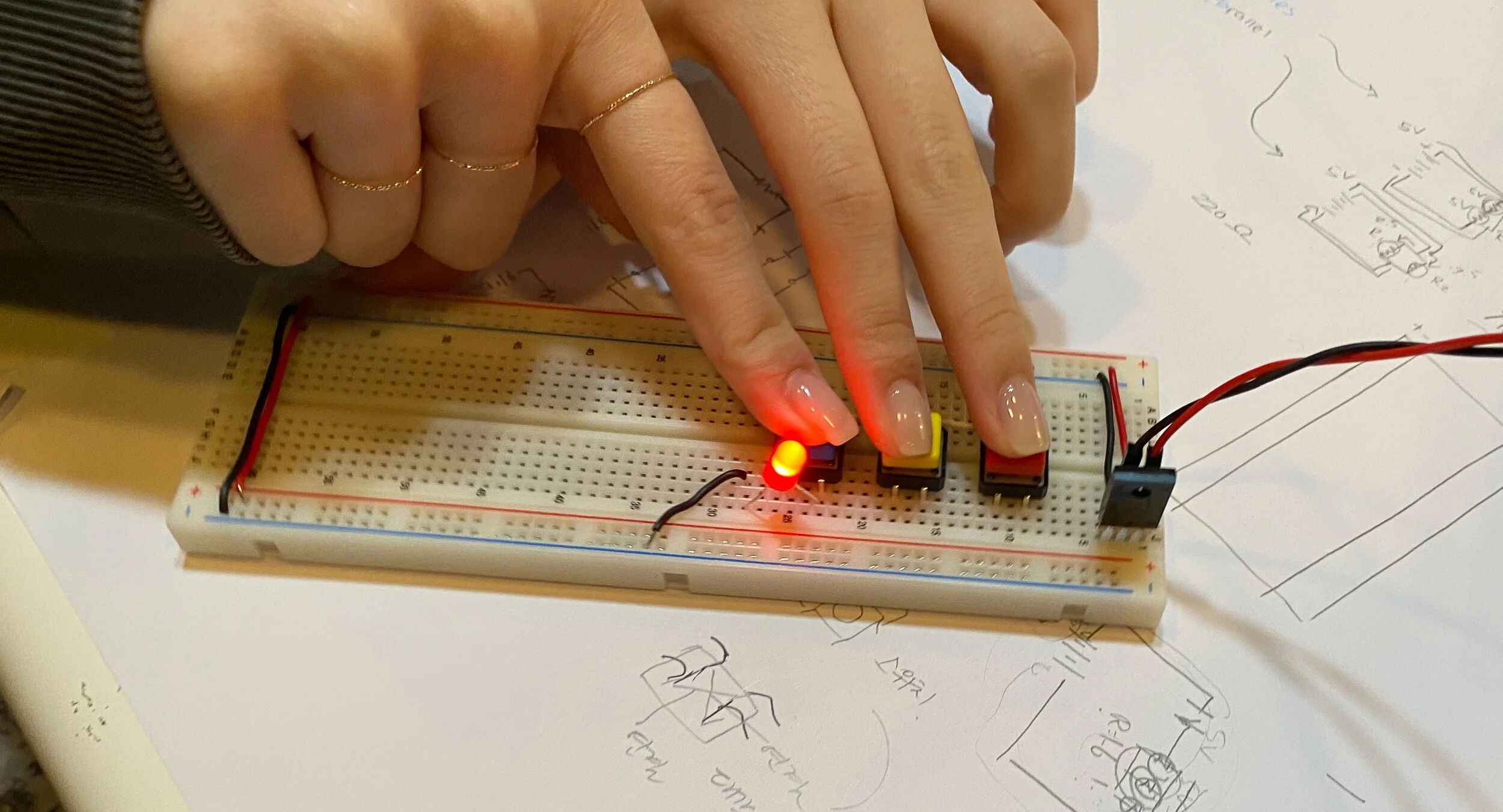
Project 1: Three Switches in Parallel
Project 2: Three Switches in Series
Project 3: Switching a Motor


Project Candle


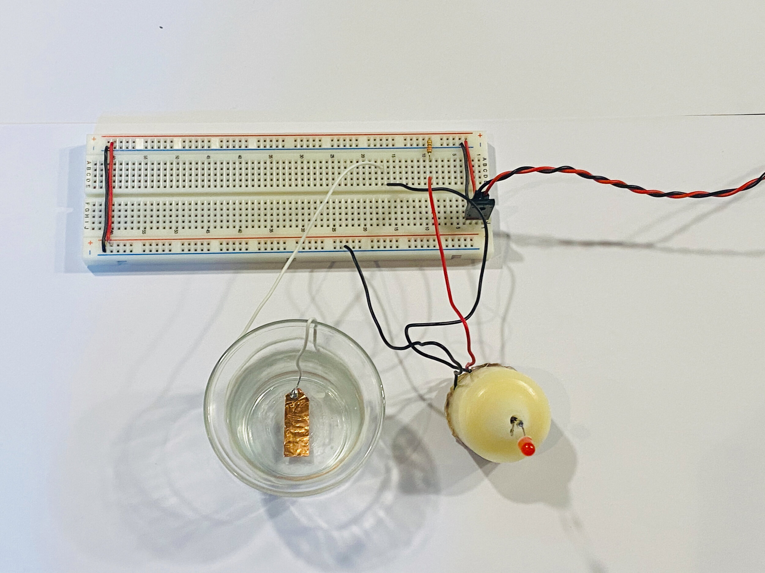
We created a “switch” using copper tape and a soldering iron. After three burns to the hand, we managed to create a switch contraption imitating a candle.
Placing copper tape on the bottom of the candle and its holder completes the circuit and lights the LED when put together.